IGNORING ENGINEERING GEOLOGY A COSTLY MISTAKE AT PENTALIA, CYPRUS
1. INTRODUCTION
The importance of geology in engineering work is self evident. Nevertheless, the input of engineering geologists is not always requested or is sometimes ignored, even when readily available.
Cyprus is an island in the Mediterranean Sea. The south west area of Cyprus has a long history of slope instability, particularly in areas of high elevation. In extreme cases the decision was made to abandon areas of instability and relocate villages (Charalambous and Petrides 1997). These decisions were based on administrative, social reasons as well as on the results of geotechnical investigations where engineering geology was an important element. Therefore, it is somewhat surprising that engineering geology was not fully considered in recent transportation projects.
Paphos, the southwestern district of Cyprus, has experienced major development in its infrastructure including several new roads linking existing villages and new developments. This paper reports on the road constructed in 2002 to link the villages of Nata, Pentalia and Panayia, in Paphos (Figure 1). The laying out of the road was based on several transportation considerations, but ignored the engineering geology of the site and the history of instabilities in this area. This omission has been costly, with the road being subject to recurring stability problems. This has resulted in considerable delays, inconvenience and cost. After exploring several stabilization options, the decision was made to move the road to more stable ground.
2. FEASIBILTY ASSESSMENT
In the early phases of a project it is unlikely that there is access to the full range of geotechnical data required for design. Instead, it is common to rely on past experience and rules of thumb. Hoek (1999) has provided an example of how engineering geology can be employed in the early stages of highway design:
“…in evaluating three alternative highway routes through mountainous terrain, the engineering geologists or geotechnical engineer would look for routes with the minimum number of unstable landforms, ancient landslides, difficult river crossings…..”.
This statement is reinforced by the observation that quite often inadequate consideration is given to engineering geology:
“…it is amazing how often a highway will be laid out by transportation engineers with more concern of lines of sight and radii of curves than for the geological conditions which happen to occur along the route.”
Unfortunately the Pentalia highway is a case where inadequate attention was given to obvious signs of instability. This had considerable consequences as the highway traverses mountainous terrain, in areas of reported landslide and seismic activity, Figure 1.

Figure 1. Hillshade map of the highway.
Nevertheless, little attention was given to engineering geology. This was somewhat surprising given that Charalambous (1991) had provided a geological and geotechnical map of the area where she clearly identified areas of disturbed ground as well as landslide scarps (Figure 2). It would appear that this information was not taken into consideration when the highway was laid out.
It was only when the first instability problems materialised during construction that input was sought from engineering geologists. Although a series of investigations were undertaken and several stabilization options explored, at the end of the day the decision was made to move the highway to what is perceived to be stable ground.
3. BACKGROUND
Construction of the road linking the villages of Nata, Pentalia and Panayia (along P453-P513) begun in late 2001. As early as January 2002 it had already displayed signs of instability. It was only then that the input of engineering geologists was requested. Figure 3 is a satellite map illustrating the highway and the area of instability.

Figure 2. Geotechnical Map of the area.
Subsequent investigations helped to record the evolution of events rather than providing a comprehensive solution. Finally, when the geotechnical studies were completed it was decided to relocate the road rather than continue to repair or attempt to stabilize it. If an engineering geology study had been undertaken prior to construction of the highway, it would have clearly contributed to a better choice of site.
3.1 Geology
The highway traverses the Mamonia Complex, a very incongruent collection of allochtonous Upper Triassic to Lower Cretaceous sedimentary formations and Upper Triassic mafic igneous rocks. The autochthonous Kannaviou formation of Campanian age is also present, comprising bentonitic clays and volcanoclastic sandstones. These are areas of low strength and have historically been associated with slope stability problems.

Figure 3. Satellite map of the highway area.
3.2 Past landslide activity
Pantazis (1969) cites several landslides in the Paphos area. These landslides have often resulted in partial or complete relocation of several villages, as reported by Charalambous and Petrides (1997). It is traditionally accepted that past
slope instability has been triggered by intensive rainfalls and the earthquakes of 1953. Northmore et al. (1986) suggest
that, in earlier times, landslides were a fact of life in these areas. A plausible reason for the observed landslide activity
was that villages were traditionally constructed near the contact of argillaceous cohesive soils and chalks where
there are natural water springs.
The highway traverses an area that has visible signs of past landslide activity. The fact that the nearby village of
Pentalia, was relocated as a result of frequent landslides, should have identified the need for an engineering geology
investigation prior to the construction of the highway. Furthermore the study by Charalambous (1991) had clearly
identified that the highway was traversing an area with visible signs of ground instability.
3.3 Seismic activity
Figure 4 is a map of the Paphos district. It illustrates the cluster of seismic activity during the last ten years in the
area traversed by the highway. In this figure seismic events are classified in three categories based on their magnitude:
less than 2.5 M; between 2.5 and 3.5 M; and between 3.5 to 4.5 M. Although the seismic history was not considered prior to the laying out of the highway, there is no evidence that the observed instabilities were influenced by seismic activity.

Figure 4. Recorded seismic events during 1997-2007 in the
vicinity of the highway.
3.4 Rainfall data
Rainfall in Cyprus is mostly confined to the winter and spring months, with the highest average annual rainfall reported on
the Troodos mountains. The road is within 24 km from the summit of the Troodos mountains. Rainfalls in this area can
be intense and are the main triggering mechanisms of landslides.
Figure 5 provides the monthly precipitation data for the station nearest to the highway at Lemona. The station is
about 5 km from the site of observed instability. Of interest, is the unusual for the area, high precipitation in December
2001, December 2002 and January 2004. This heavy precipitation had an adverse impact on the stability of the highway.

Figure 5. Rainfall data from the nearest weather station to
the highway.
4. LANDSILDE TIMELINE
The road linking the villages of Nata, Pentalia and Panayia (along P453-P513) had already displayed signs of instability
in January 2002 while the road was still under construction. The development of long cracks in the road, illustrated in
Figures 6 and 7 was a cause of concern. The consensus was that these were linked to higher than usual rainfalls and
snowfalls during December 2001. Following some remedial measures the road was completed and opened to traffic.

Figure 6. Initial signs of instability, January 2002

Figure 7. Initial signs of instability, January 2002.
It was not long after completion of the highway that several new sets of cracks appeared on the surface of the asphalt. It
was suggested that the slip surface was in the argillaceous substratum below the road and talus. By April 2003 it was
decided to record these localized cracks (Figure 8 from Kyriakou 2003). These extended a long stretch of the
highway as well as in the embankment. As shown in Figures 9 and 10 these cracks were long and quite deep cutting
through the asphalt and substrata layers. Figure 11 illustrates the development of a major crack in the embankment of the highway.
At this point in time it was accepted that the highway was in an area of previous landslide activity. It was also recognized that it was necessary to consider adequate measures to ensure the operation of the highway. It was then postulated
that the intensive rainfalls could have re-activated a previously dormant landslide. The situation was aggravated
as a result of poor draining. Furthermore, it was recognized that the road embankment was directly over low strength
materials.

Figure 8. Recorded fissures along the highway, Scale 1: 1000, April 2003

Figure 9. Signs of instability, April 2003.

Figure 10. Signs of instability, April 2003

Figure 11. Signs of instability, April 2003
Given that damage to the highway was over 300 m long, and the fact that this is a rural area, it was not possible to justify major stabilization works. Instead, it was decided that a stabilizing toe, associated with improved drainage, may provide a satisfactory option. Preliminary limit equilibrium analysis suggested that the use of a stabilizing toe may have been adequate for the assumed shallow failure.
4.1 Data collection and instrumentation
Due to a variety of administrative decisions there was a delay in collecting more field data. Nevertheless, by October 2004 five cored boreholes ranging from 30 to 35 m depth were driven along two sections of the highway, Figure 8. The encountered layer of talus was up to 8 m deep, and characterized by the presence of whitish clasts of chalks of variable size and shape in a loose to medium dense calcareous silty matrix. This was underlain by the mélange typical of the region.
The mélange is characterized by reddish brown clayey silt containing clasts of the Mamonia formation. Of interest, and cause of alarm, was the evidence of slickenside at different depths in the mélange observed in boreholes A1, A2 and A3.
4.2 Piezometric Data
Two piezometers were installed in boreholes A1 and B3. The recorded levels are shown in Figure 12. These confirmed the perception of a perched water table within the talus, overlying the impermeable melange.

Figure 12. Observation wells.
The level of the perched water table is controlled by the seasonal precipitation and can fluctuate considerably. In the same geological setting it is not unusual to note the presence of seasonal and temporary springs along the talus-melange contact or within the highly weathered and disturbed mélange.
4.3 Ground displacement measurements
In order to determine the slip surface of the landslide four inclinometers were installed in boreholes A2, A3, B1 and B2. Figure 13 provides some of the early readings for borehole A3. Unfortunately the B2 inclinometer was broken at 3.20 m from ground surface, probably due to major displacement. In retrospect it might have been advantageous to locate the inclinometers at different locations along the length of the highway that showed signs of instability.

Figure 13. Displacement measurements in borehole A3, initial survey Nov. 23 2004 and final reading Nov. 9 2006.
4.4 Impact of delays
It should be recalled that the first signs of instability were reported during construction of the highway in January 2002. Although some more data were collected in fact no effective remedial action was taken other than “filling” the cracks in the asphalt. By the summer of 2005 the situation had deteriorated considerably as shown in Figures 14 and 15 resulting in more areas of instability.
Following the construction of a terrain model, and further observations it was recognized that the second slip surface,
at a distance 80 m further from the first vertical cut, was deeper than originally assumed. This prompted further analyses and a re-evaluation of the overall strategy to return this road stretch to circulation. A deeper failure surface would require a bigger volume of buttress. It was also recognized that it would probably be necessary to expropriate more land for these purposes.
The use of reinforcing piles, which was given consideration in the past, was an expensive option. In order for the piles to
be successful in strengthening the slip surface they would have to intersect it. In fact an economic analysis of the associated costs for the different remedial measures suggested that in light of the new information, serious consideration should be given to re-routing this stretch of the road.
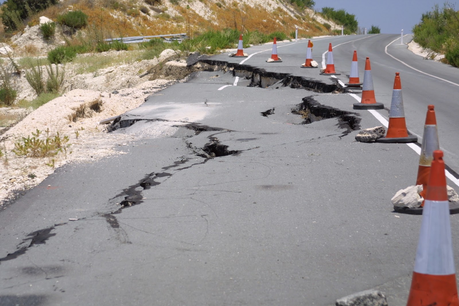
Figure 14. Deterioration of the highway, 2005.

Figure 15. Deterioration of the highway, 2005.
In the meantime the situation continued to deteriorate to the level where a horseshoe potential failure surface was identified, Figure 16. It would appear that the cracks in the highway could be extended to old landslide scarps. Furthermore, the highway was unraveling and the cracks opening up further, Figure 17.

Figure 16. Horseshoe failure.

Figure 17. Widening cracks, November 2006
4.5 Comprehensive Stability Analysis
A comprehensive stability analysis was undertaken in 2005, described in detail by Hadjigeorgiou et al. (2006). The limit equilibrium analysis used Slide and the finite element employed Phase2, both available from Rocscience (2005). The viability of the stabilization options was investigated using as input the results of triaxial tests. At this time, based on field observations it was recognized that it was necessary to investigate deeper slip surfaces than the original analysis.
The same geometrical models used in the limit equilibrium analysis in Slide were introduced into the Phase2 finite element analysis package. An example is illustrated in Figure 18 where the maximum shear strain was determined. The strength reduction factor technique was also used to visualize the progression of failure within the slope. The zone of failure was visualised by plotting a total displacement graph. Figure 19 plots the total displacement concentrations and the resulting deformed mesh. The resulting slope geometry closely resembled the observed field conditions.

Figure 18. Section B-B illustrating the development of
maximum shear strain concentrations.

Figure 19. Section B-B deep failure illustrating the
development of total displacement concentrations.
5. ALIGNING A NEW ROAD
The construction of a new road, as the finally adapted solution, has not yet began, although the construction designs are now completed. Figure 20 provides a summary of the available information for the stretch of instability of the Pentalia highway. It shows the existing highway as well as the surficial deposits of talus and melange. The overhanging chalks over the highway are also noted.
The location of boreholes A1, A2 and A3 as well as B1, B2 and B3 are also identified. Of interest however are the signs
of all landslide escarps in the chalks and the location of seasonal springs just below the highway in the talus.
The new road alignment, several meters from the existing road, is also shown in Figure 20. The new alignment is well outside the zone of cracks and settlements that were noted on the existing road. Nevertheless, it is still within an area of
past instability, and is still in the same geological conditions. The rational of the transportation engineers is that the
existing road embankment may act as a stabilizing agent. This was not however demonstrated by further analysis. The
new works also involve a well designed and effective drainage system along the road. Up the road there will be a diversion channel to reroute surface water away from the road. Whether this shifting of the road, even with improved drainage measures will be sufficient to avoid future instability remains to be seen.
6. CONCLUSIONS
The importance of engineering geology in laying out a highway in an area that has been recognised as landslide prone should have been evident. Nevertheless, the Pentalia highway was laid without detailed engineering geology investigations. Furthermore, the existing geological and geomorphologic data appear to have been ignored.
Once instabilities appeared, it was decided to repair and continue construction of the highway. This approach did not
alleviate the problem. The results of subsequent investigations provided plausible explanations of the failure mechanisms, but were not followed by prompt intervention or the implementation of effective stabilization measures. Once all the studies were completed and all options explored the decision was made to move the highway, Figure 20. Nevertheless, the proposed new highway alignment is still in a landslide prone area. Whether this will succeed in securing the long term stability of the highway remains to be seen.
In retrospect, it would have been beneficial if a comprehensive engineering geology investigation had preceded the marking of the highway in this particular area. Furthermore, once the early instability signs were noted it may have been advantageous to respond in a more timely fashion. Ignoring engineering geology resulted in considerable costs, delays. It should be noted that following this case study a recommendation was issued to undertake full geotechnical investigations prior to laying out any roads in landslide prone areas.

Figure 20. Geological-geotechnical map identifying the geology, old landslide scarps, the boreholes and the existing and new road alignment.
No comments:
Post a Comment